- Catalogues
- CARRIER commercial
- Indoor Air Handlers
- Produits
- Catalogues
- News & Trends
- Salons
Indoor Air Handlers
1 /44Pages

Indoor Air Handlers
1 /44Pages
Extraits du catalogue

Product Data Indoor Air Handlers Nominal 1,800 to 15,000 cfm 39LA,LB,LC,LD,LF,LG,LH03-25 Indoor Air Handlers © 2019 Carrier Corporation Form 39L-8PD Rev. B
Ouvrir le catalogue en page 1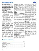
Features/Benefits Carrier delivers the air handler components for many stringent specification requirements. The 39L Series air handlers are compact and fully assembled; they combine versatility with economical, dependable performance. Carrier 39L Series air handlers offer: • Horizontal and vertical draw-thru arrangements for heating, cooling, ventilation, and VAV (variable air volume) applications • Small footprint assures rigging ease and reduced space requirements • High-efficiency fan minimizes surging and turbulence and reduces operating costs • Exclusive Nu-Fin coil surface provides peak...
Ouvrir le catalogue en page 2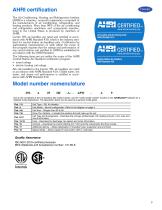
AHRI certification The Air-Conditioning, Heating and Réfrigération Institute (AHRI) is a voluntary, nonprofit organization comprised of the manufacturers of air conditioning, refrigeration, and heating products. More than 90% of the air conditioning and refrigeration machinery and components manufac-tured in the United States is produced by members of AHRI. Carrier 39L air handlers are rated and certified in accordance with AHRI Standard 430, which is the industry standard for central station air-handling units. Certification by participating manufacturers of units within the scope of this program...
Ouvrir le catalogue en page 3
LEGEND — Combination — Preheat — Position PRE-HEAT WATER OR PRE-HEAT STEAM POSITION 4, UNIT CONFIGURATION MODEL (Component Sequence Also Shown) Model number nomenclature (co
Ouvrir le catalogue en page 4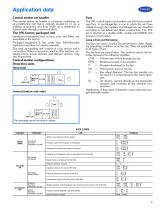
Application data Central station air handler The central station air handler is a heating, ventilating, or air-conditioning unit that is centrally located in, or on, a building or structure and from which air is distributed to desired areas through a system of ducts. The 39L factory packaged unit Individual components, such as fans, coils, and filters, are assembled at the factory. Packaged equipment is less costly than field-fabricated equipment and does not require assembly. The basic air-handling unit consists of a fan section and a coil section. Other components, such as filter sections,...
Ouvrir le catalogue en page 5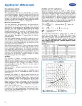
Fan sélection criteria System requirements The major factors that influence fan sélection are airflow, external static pressure, fan speed, brake horsepower, and sound level. Additional system considerations include the fan control method, overloading, and non-standard air density. Fan selection for air-conditioning service usually involves choosing the smallest fan that provides an acceptable level of performance, efficiency and quality. Pressure considerations The static pressure is the resistance of the combined system apart from the fan. Contributors to static pressure include other components...
Ouvrir le catalogue en page 6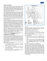
Sound considerations The fan is one of the main sound sources in an air-conditioning system. Other sources of sound include the duct system and terminals, because they generate turbulence in the air flowing through them. Simply estimating fan sound does not give an accurate picture of total system sound, but because fan sound is a major component of system sound, fan sound should be minimized. To minimize its sound generation, a fan must be correctly sized and should be selected to operate at or near peak efficiency. Oversized fans can generate much higher sound power levels than necessary, especially...
Ouvrir le catalogue en page 7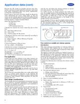
Application data (cont) Because the 39L Series air handlers all have their fans, motors, and drives located within the airstream, heat losses from these components affect the power requirements, cooling load, and heating load. Power losses in the motor and drive should be allowed for when determining the motor output (bhp), so that the motor can be correctly sized and so that the additional heat output can be subtracted from cooling capacity or added to heating capacity. A typical example follows: Given Fan Operating Point: 13,224 cfm 9.6 Fan bhp 3.0% estimated drive loss Calculate the required...
Ouvrir le catalogue en page 8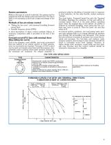
System parameters Before a fan type or control is selected, the system must be analyzed at both the design point and part load. The fan is likely to be operating at part load a large percentage of the time. Methods of fan air-volume control • “Riding the fan curve” with terminal throttling (forward curved fans) • Variable frequency drives (VFDs) A short description of these control methods follows. A summary comparison table is provided at the end of the section. Forward-curved (FC) fans with terminal throt-tling (riding fan curve) This is the simplest, most reliable, and most economical first-cost...
Ouvrir le catalogue en page 9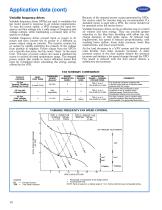
Variable frequency drives Variable frequency drives (VFDs) are used to modulate the fan motor speed in response to air volume requirements. To vary the motor speed, a VFD changes the input frequency and line voltage into a wide range of frequency and voltage outputs, while maintaining a constant ratio of frequency to voltage. Variable frequency drives convert input ac power to dc power and then convert the dc power to a different ac power output using an inverter. The inverter creates the ac output by rapidly switching the polarity of the voltage from positive to negative. Power output from the...
Ouvrir le catalogue en page 10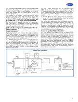
The Variable Frequency Fan Speed Control chart illustrates the results of fan speed reduction as operation shifts from Point A to Point B. If duct pressure begins to fall due to terminal units opening, the duct sensor signals the VFD to increase fan speed. This method of air volume control permits fan speed reduction down to as low as 10% of the design speed. With FC fans riding the fan curve at the lower rpm, airflow may be as low as 10% of peak design, as long as motor rpm is not less than 1/6 of motor synchronous speed. The method may be applied to any size VAV system with any type of fan....
Ouvrir le catalogue en page 11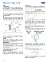
Application data (cont) Coils Coil definitions A coil, as the term is used with air-handling equipment, is a heat exchange device. A heating or cooling medium passes through the coil, where it either rejects heat to or absorbs heat from the airstream passing over the coil, depending upon the relative temperatures of medium and airstream. Tube The tube is a small-diameter pipe through which the heating or cooling medium passes as it rejects or absorbs heat. Coil tubes are generally constructed of copper but may be made of other metals. Fin The coil fin is a thin metal plate attached to the tube...
Ouvrir le catalogue en page 12Tous les catalogues et fiches techniques (PDF) CARRIER commercial
 40UV-UH-14SI
32 Pages
 42B-6SI
24 Pages
 A WORLD OF COMFORT PRINT
10 Pages
 A WORLD OF COMFORT (2025)
20 Pages
 AirStream™ Room Fan Coils
4 Pages
 19DV
19DV32 Pages
 30XA
30XA136 Pages
 30RAP
30RAP104 Pages
Catalogues archivés
 The CRRSA Act (ESSER I)
2 Pages
 AERO® Air-Handling Units
4 Pages
 Axis™ Overhead Air Terminals
4 Pages
 Carrier-Catalogue-2018-2019
940 Pages
 2019 Carrier Ductless
88 Pages
 Carrier VRF
44 Pages
 Axis Overhead Air Terminals
2 Pages
 Roomtop® 50AH036-072
24 Pages
 OMNIZONE™ 50BV020-064
64 Pages
 A World of Comfort 2015
2 Pages
 Low Noise Type CABINET FAN
16 Pages
 Performance 16 Heat Pump
4 Pages
 ComfortVIEW 3
6 Pages
 VVT Zoning System
8 Pages
 Heat Reclaim Chillers
2 Pages
 Airstream Unit Ventilators
2 Pages
 Airstream Room Fan Coils
2 Pages
 Aero Air-Handling Units
2 Pages
 17DA Centrifugal Chiller
2 Pages
 AXIS? Overhead Air Terminals
3 Pages
 Comfort? Series
2 Pages
 GEMINI? 38AKS028-044
40 Pages
 i-Vu Open Standard & Plus
2 Pages
 A World of Comfort
2 Pages
 AIRSTREAM™ Room Fan Coils
3 Pages
 ROOMAIR CONDITIONERS
6 Pages
 Water-Cooled Chillers
3 Pages
 Antimicrobial Solutions
3 Pages


- Pompe à chaleur CARRIER
- Pompe à chaleur résidentielle
- Unité de climatisation
- Pompe à chaleur aérothermique
- Thermostat
- Détecteur apparent CARRIER
- Pompe à chaleur d'extérieur
- Thermostat blanc
- VMC
- Détecteur blanc CARRIER
- Détecteur professionnel CARRIER
- Thermostat programmable
- Armoire de climatisation professionnel
- Unité de climatisation split
- Thermostat pour chauffage
- Thermostat numérique
- Pompe à chaleur inverter
- Thermostat mural
- Climatiseur réversible
- Thermostat avec affichage numérique